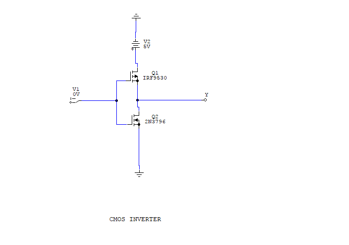
When the input of nMOS is smaller than the threshold voltage (V in V TO and if following conditions are satisfied. Mason Lecture Notes .3 Transistor Switching Characteristics. Substrate of the nMOS is connected to the ground and substrate of the pMOS is connected to the power supply, V DD. CMOS logic circuit CMOS logic circuit V VDD logic 1 voltages logic 0 voltages undefined. The input is connected to the gate terminal of both the transistors such that both can be driven directly with input voltages. This configuration is called complementary MOS (CMOS).
#Cmos inverter logic driver#
Here, nMOS and pMOS transistors work as driver transistors when one transistor is ON, other is OFF. The CMOS inverter circuit is shown in the figure. The voltage transfer characteristics of the depletion load inverter is shown in the figure given below − CMOS Inverter – Circuit, Operation and Description The output is switched from 0 to V dd when input is less than V th. V th is the inverter threshold voltage, which is V dd /2, where V dd is the output voltage. In digital circuits, binary arithmetic and mathematical manipulation of switching or logic functions are best performed with the symbols 0 (zero) and 1 (one). Using positive logic, the Boolean value of logic 1 is represented by V dd and logic 0 is represented by 0. An inverter is a logic element that reverses the applied signal. Here A is the input and B is the inverted output represented by their node voltages. The logic symbol and truth table of ideal inverter is shown in figure given below. This is certainly the most popular at present and therefore deserves our special attention. V1 Amplifier, V2Aa, Feedback Network, Ff, Figure 1. In this chapter, we focus on one single incarnation of the inverter gate, being the static CMOS inverter - or the CMOS inverter, in short. Theory of Oscillators In principle, an oscillator can be composed of an amplifier, A, with voltage gain, a, and phaseshift,, and a feedback network, F, with transfer function, f, and phase shift, (see Figure 1). The analysis of inverters can be extended to explain the behavior of more complex gates such as NAND, NOR, or XOR, which in turn form the building blocks for modules such as multipliers and processors. Why not give the output of a circuit to one large inverter We cannot use a big inverter to drive a large output capacitance because, who will drive the big. The electrical behavior of these complex circuits can be almost completely derived by extrapolating the results obtained for inverters.


Once its operation and properties are clearly understood, designing more intricate structures such as NAND gates, adders, multipliers, and microprocessors is greatly simplified. It consists of 2 MOS-FETs: An N-channel on the bottom and a P-channel on top. It is the most essential part of all integrated circuits. The inverter is truly the nucleus of all digital designs. The CMOS inverter is the basic form of CMOS. A CMOS inverter is a device that is used to make logic functions.


 0 kommentar(er)
